
Last Updated: June 9, 2026 | By the E3 Aviation Association Editorial Team
Most pilots who lose a vacuum system in flight never see it coming. The suction gauge drifts low. The attitude indicator leans a few degrees. The heading gyro starts to wander. None of it screams emergency.
That quiet failure mode is what makes a vacuum system failure one of the most dangerous mechanical events in a piston single. It’s driven a generation of FAA safety guidance, partial-panel training, and avionics replacement policy.
This guide walks through what a vacuum system actually does. How it fails. What the cockpit looks like at each stage. How to recover when it happens in IMC. And how to decide between an overhaul, a backup attitude indicator, or a full electric replacement at next annual. It’s written for the owner-pilot flying a 172, Cherokee, Bonanza, or any other airframe that still leans on a single engine-driven vacuum pump.
We won’t pretend this is a simple subject. A vacuum system failure can cause a loss-of-control accident in IMC. Or it can be a non-event on a clear day. The difference is recognition speed and partial-panel proficiency. That’s the gap this article closes.
What the Vacuum System Actually Does in Your GA Airplane
The vacuum system in a typical piston single is built around a single dry air pump driven by the engine accessory case. It pulls filtered air across two gyroscopic instruments — the attitude indicator (artificial horizon) and the heading indicator (directional gyro). The airflow spins each gyro fast enough to hold its reference plane in space.
The system is deliberately simple. A regulator holds suction at roughly 4.8 to 5.2 inches of mercury. A vacuum gauge in the panel shows you the working value. A central air filter and individual instrument filters keep dust out of the gyros. Hoses route filtered air from the instruments to the pump. The pump exhausts overboard. On most installations, there’s no warning system beyond that one suction gauge.
That architecture matters. It puts the attitude indicator and the heading indicator on a shared single point of failure. If the pump quits, both gyros lose drive. The turn coordinator stays alive — it runs on the electrical bus, not on vacuum. The magnetic compass is unaffected. So a vacuum system failure doesn’t strip the panel. It strips the two gyros most pilots actually scan first.
That’s the cockpit problem that defines this article. You still have airspeed, altimeter, vertical speed, turn coordinator, and compass. What you lose is the picture in the middle of the panel that most pilots learned to fly by.
How a Vacuum System Failure Begins — and Why It Hides
The textbook failure of a dry air pump is mechanical. Carbon vanes inside the pump wear down with hours. They shed material. Eventually one or more vanes fracture, the rotor stops spinning, and suction drops to zero. That can happen instantly when a vane breaks. Or it can creep in over many flights. The vanes lose contact area. The regulator can’t hold the set point anymore.
What makes a vacuum system failure dangerous is the second pattern. The pump doesn’t have to die all at once. It can lose efficiency slowly. The gyros downstream of it have enough inertia to keep spinning long after suction drops below the working range.
So the attitude indicator may keep pointing roughly straight while the gyro decelerates. It leans a few degrees off true. It drifts slower than the airplane actually moves. The pilot reads the leaning attitude as real and trims the airplane to match. By the time the failure’s recognized, the airplane is already off heading, off altitude, or in an unusual attitude.
The FAA captured this pattern in Advisory Circular 91-75. That’s the policy that opened the door to electric attitude indicators as a substitute for the rate-of-turn indicator under 14 CFR 91.205. The AC explicitly calls vacuum system failure insidious. The gyro fails slowly enough to be misleading. That single sentence shaped a generation of partial-panel training.
The third pattern is filter-driven. A clogged central air filter or instrument filter restricts the pump’s airflow. Suction drops. The gyros run slow. This one’s preventable. Most vacuum systems specify central filter replacement at the annual or at a calendar interval — often 500 hours or two years. Skip it, and the pump pays the bill.
The Cockpit Signature of a Vacuum System Failure
The fastest way to recognize a vacuum system failure is the suction gauge. If it reads below the green arc (typically below 4.5 in.Hg) in cruise, that’s the failure announcing itself. The problem is that most pilots don’t scan the suction gauge. It sits in a corner of the panel and gets ignored once the airplane’s established.
So the cross-check has to do the work. Here’s the signature you’re looking for.
Attitude indicator drifts off level. The airplane is straight and level by every other reference. But the attitude indicator shows a slight bank or pitch offset that grows as the gyro decelerates. The flag, if installed, may or may not drop.
Heading indicator stops tracking the compass. The heading indicator is normally reset against the magnetic compass during cruise. If the spread between the two grows steadily and can’t be corrected, the heading gyro is winding down.
Turn coordinator disagrees with the attitude indicator. The turn coordinator runs on electricity and is independent. In coordinated flight with wings level by the turn coordinator, the attitude indicator should also show wings level. A persistent disagreement is the signature.
Suction gauge below green. This is the confirming cue. Combined with any one of the three above, it’s diagnostic.
We’ll be straight with you: in single-pilot IMC, the failure rarely presents as a clean textbook case. It presents as a slow disorientation. The airplane starts banking. The pilot doesn’t understand why. That’s why the partial-panel scan has to be a habit, not a fallback. If your only partial-panel practice is the instrument proficiency check, the recognition window in a real failure runs short.
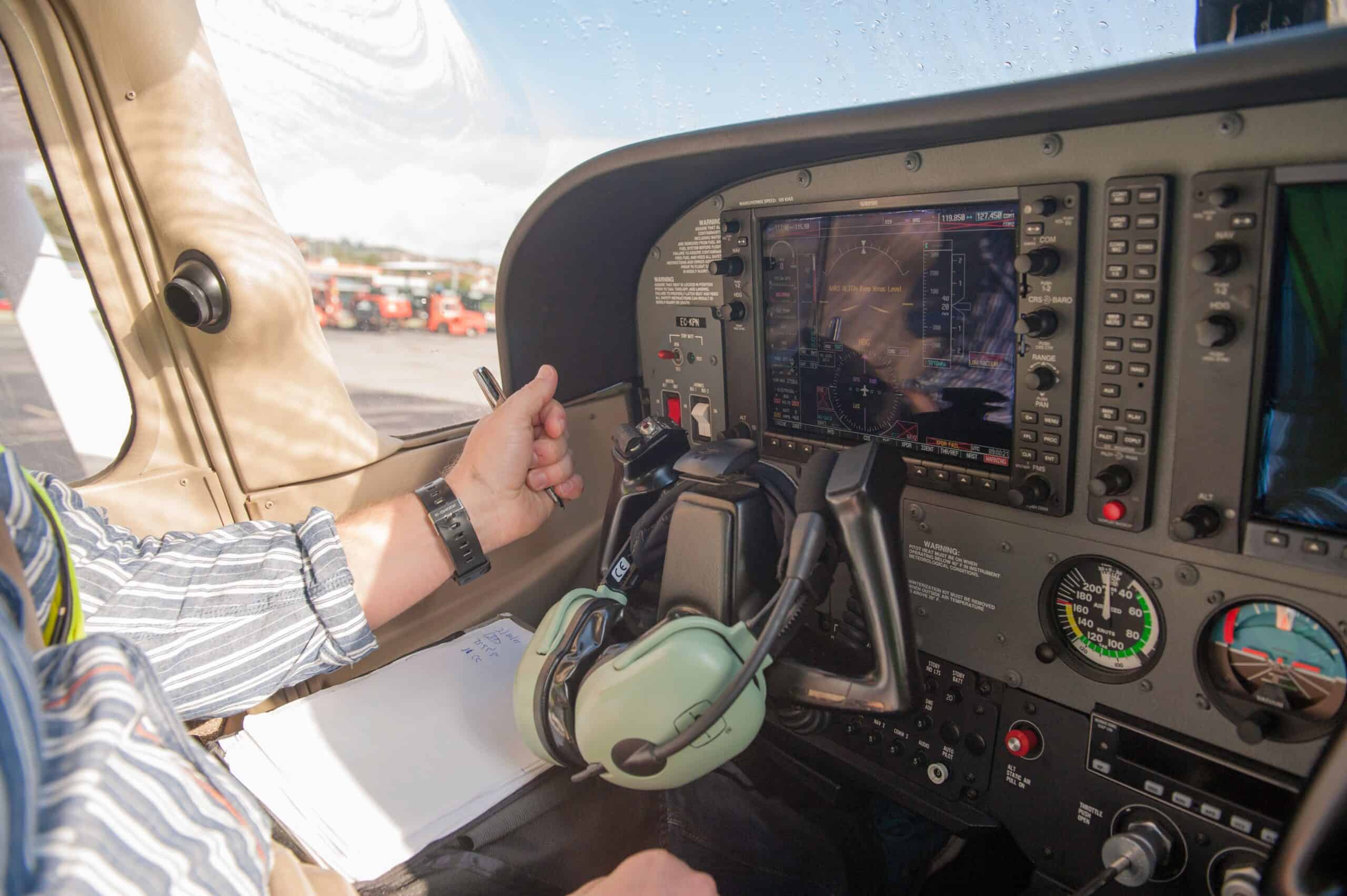
A Piper cockpit panel: this is the airframe class where partial-panel proficiency decides the outcome of a vacuum system failure.
Partial-Panel Recovery After a Vacuum System Failure
Once a vacuum system failure is recognized, the recovery framework is straightforward but demands discipline. The attitude indicator and heading indicator are both unreliable. Cover them with the standard partial-panel cover if you have one. Or commit to ignoring them. Then build the new scan around the instruments that still work.
Pitch is held with the altimeter and the vertical speed indicator. The airspeed indicator backs up the pitch picture. Power plus pitch yields a predictable airspeed for the configuration you’re flying.
Bank is held with the turn coordinator. The wings-level reference is the miniature airplane symbol centered between the index marks. Standard-rate turns are flown by aligning the wing tip with the index.
Heading reference comes from the magnetic compass — with full awareness of compass turning and acceleration errors. The standard north-east-west-south errors apply. A timed turn at standard rate is often more reliable than chasing the compass.
The recovery procedure in AC 91-75 is the same one taught for any unusual attitude on partial panel. Reduce power to idle if airspeed is increasing and pitch is below the horizon. Level the wings to the turn coordinator. Slowly raise the nose to a level pitch by reference to the altimeter and VSI. Then restore power. The order matters. Power before pitch can dig the dive in deeper.
Here’s what most pilots get wrong on partial-panel recovery: they try to keep flying the route. The first move after recovery is to stabilize the airplane. Get straight and level by the surviving instruments. Only then think about navigation.
Honestly, the right move in single-pilot IMC after a confirmed vacuum failure is usually a controlled diversion. Nearest VFR airport. Not pressing on to the planned destination. AVweb’s accident probe on losing attitude makes the same point. The fatal cases almost always involve a pilot trying to continue rather than divert.
If ATC is available, declare the failure. The phrase is “partial panel, no attitude, no heading.” Ask for vectors at a comfortable altitude in VMC if possible. Keep transmissions short. Fly the airplane first, talk second.

The Maintenance Side of Vacuum System Failure
Most vacuum system failures are preventable. The prevention happens at the annual or at a calendar interval — not in the cockpit. The three failure points the maintenance schedule targets are the pump, the hoses, and the filters.
Dry air vacuum pumps from the major manufacturers (Tempest, Rapco, Aero Accessories) all publish recommended replacement intervals. The most common recommendation is 500 hours time in service or 6 years from installation, whichever comes first.
The 6-year calendar limit catches the airframe that doesn’t fly much. Statistically, the low-time airframe is the worst case. The vanes get brittle from long idle periods. Owner-pilots who fly less than 80 hours per year should treat the calendar interval as the binding constraint.
Hoses are the second wear item. Rubber hoses age from heat, oil exposure, and ozone. Most manufacturers recommend hose replacement on the same 6-year calendar as the pump. A cracked or collapsed hose causes a partial restriction that mimics a worn pump but is actually a hose problem.
The central air filter and individual instrument filters are the third wear item. Central filters are typically replaced at the annual or at 500 hours, whichever comes first. Instrument filters often run on a 1,000-hour or three-year cycle. Skipping filter replacement is the cheapest way to wreck an otherwise good pump. The dirty air destroys the carbon vanes.
The pre-buy inspection on any vacuum-equipped airplane should include a log review for pump, hose, and filter replacement dates. A 12-year-old pump in a low-time airframe is a finding that affects the price. We cover the broader framework in our owner-pilot preventive maintenance guide. The same Part 43 logic that lets an owner change oil also covers vacuum filter replacement on most installations.
The shop-side cost is real but bounded. A new dry air pump in 2026 runs roughly $700 to $1,200 depending on the model. Hoses run $200 to $400 in materials. Labor for a pump R&R is usually 2 to 4 hours. Plan on a $1,500 to $2,500 line item every 500 hours or 6 years for a fully maintained vacuum system. That’s before you talk about a backup.
Backup Options That End the Vacuum System Failure Problem
The cleanest answer to a vacuum system failure is to remove the vacuum system from the failure tree entirely. There are three real options in 2026. The right one depends on how much of the panel you’re willing to touch.
The Cheapest Path: An Electric Standby Attitude Indicator
It’s the cheapest path. A small electric attitude indicator with its own battery backup sits next to the existing vacuum attitude indicator. The vacuum system stays in the airplane. The original attitude indicator remains primary. The electric unit provides an independent reference if the vacuum fails. Units from Mid-Continent, RC Allen, and Garmin run roughly $2,500 to $5,500 plus install. This preserves the original panel and is the easiest STC path for older airframes.
The Middle Path: Electric Primary, Vacuum Demoted to Backup
AC 91-75 opened the door for an FAA-approved electric attitude indicator to replace the rate-of-turn indicator required under 14 CFR 91.205(d)(3). That policy lets owners install an electric attitude indicator with backup battery as the primary attitude reference. The vacuum system gets demoted to a backup role — or removed entirely. The logic is documented in the FAA’s policy statement on vacuum system replacement. That policy simplified field approvals for this swap.
The All-In Path: Full Glass Upgrade
A modern primary flight display with an AHRS and a battery backup replaces both vacuum gyros and the vacuum system. The same logic applies to a Garmin G500 TXi, a GI 275 pair, a Dynon Certified setup, or an aftermarket G1000 NXi installation. The vacuum pump, hoses, and central filter come out. Costs run $20,000 to $60,000 depending on the panel. But the vacuum maintenance burden drops to zero. The partial-panel scenario changes character entirely.
Our take on the three options. Fly hard IFR more than 20 hours a year. Plan to keep the airframe a decade. The electric primary or glass upgrade pays for itself in risk reduction. If you fly day VFR with occasional IFR currency runs, an electric standby attitude indicator buys most of the safety. At one-fifth the price. The worst answer is to leave a vacuum-only panel in place and call it good. The MTBF on a traditional vacuum-driven attitude indicator is only a few hundred hours. That’s the number you’re betting on every time you launch into IMC.
The 2026 Buyer’s Framework for Vacuum-Equipped Aircraft
If you’re shopping for a 172, a Piper Cherokee, a Beechcraft Bonanza, or a Mooney, you’re almost certainly buying a vacuum-equipped airplane. The pre-buy framework comes down to four questions.
First — when was the pump last replaced, and what’s its current time in service? A pump within 200 hours of the 500-hour limit is a near-term replacement cost. A pump within one year of the 6-year calendar limit is the same. Build it into the offer.
Second — when were the hoses and filters last replaced? Look for log entries at the same interval as the pump. A pump that was changed without changing the hoses is a finding. The hoses sit upstream of the new pump. Any debris in them will be ingested.
Third — what does the suction gauge read at idle, at run-up, and at cruise on the test flight? Below 4.5 in.Hg at cruise is a flag. A wandering needle is also a flag — it suggests a regulator or a leaking hose. The gauge is the cheapest diagnostic on the airplane.
Fourth — does the airplane already have an independent backup? An electric standby attitude indicator with its own battery is a value-add. A full glass panel is more than a value-add — it changes the buyer-side risk math.
For pilots moving from a basic trainer to a complex IFR airplane, our transition training analysis applies. A vacuum-equipped airplane demands proficient partial-panel skills. If those skills aren’t current, the transition program should include them before the first IFR mission in the new airframe.
How a Vacuum System Failure Shows Up in the Accident Record
The accident record on vacuum system failure is consistent across the last two decades. The NTSB database carries a recurring pattern. Vacuum pump fails in IMC. The pilot doesn’t recognize the failure quickly enough. The airplane enters an unusual attitude. The pilot can’t recover on partial panel.
Aviation Safety magazine’s loss-of-control feature documents the same pattern. Roughly three spatial-disorientation accidents per year track to vacuum or gyro instrument failures. A low absolute number. But the fatality rate when it happens is high.
The contributing factors in the docket are predictable. Pumps operated beyond manufacturer time limits. Pilots who hadn’t flown partial-panel since their last IPC. Single-pilot IFR with no backup attitude indicator. Continued flight into IMC after the failure was recognized — rather than diversion.
Compare that against the 2026 GA fatal accident rate and the broader loss-of-control prevention literature. The conclusion writes itself. Vacuum system failures are rare. The recovery is teachable. The infrastructure to remove the failure entirely exists and is affordable. The accident record stays ugly because pilots and owners keep treating the vacuum system as set-and-forget hardware. It isn’t.
Our Take on Vacuum System Failure in 2026
The honest answer for the 2026 owner-pilot is that the vacuum system is a 1950s solution still flying in 2026 airframes. The replacement economics didn’t make sense for thirty years. They make sense now. Electric attitude indicators with battery backups have come down in price. The STC paths are well-established. The FAA policy framework (AC 91-75 plus the vacuum replacement policy statement) explicitly favors the swap.
If you’re flying IMC in a vacuum-only panel without an electric standby, the math isn’t in your favor anymore. The cost of the standby is a fraction of the cost of one repair after a hard recovery. It’s a tiny fraction of the cost of one fatal accident. We aren’t in the business of selling avionics. We’re in the business of telling pilots what the safer airplane looks like in 2026. The safer airplane has an independent attitude reference.
For the day-VFR pilot, the picture is different. A vacuum system failure in clear VMC is a non-event. You see the horizon outside the airplane and you fly by it. The maintenance still matters — a failed vacuum system is also a failed heading indicator and a degraded panel for the next pilot. But the safety margin is wide. Keep the pump and hoses on schedule. Replace the central filter at the annual. Let the airplane be what it is.
For everyone in between, partial-panel proficiency is the safety margin. The VFR pilot who flies the occasional IFR currency mission. The owner who launches into marginal VFR more often than the family thinks. The renter who flies different airframes month to month. Practice it on every flight review. Practice it on every IPC. The recognition habit is what closes the gap between a vacuum system failure that becomes a story and one that becomes a statistic.
Frequently Asked Questions About Vacuum System Failure
How long does it take to recognize a vacuum system failure in IMC?
Most pilots recognize it within 30 to 90 seconds of the gyros starting to slow. That assumes they’re scanning the turn coordinator and suction gauge as part of their normal cross-check. A pilot focused on the attitude indicator alone may not catch the failure. Not until the airplane has already entered an unusual attitude. That’s the failure mode behind most of the fatal accidents in the NTSB record.
Is a vacuum system failure a reason to declare an emergency?
In IMC, yes. Use this phrase: “partial panel, no attitude, no heading, request vectors to VMC.” Declaring early gets you priority handling. It lets ATC keep traffic away while you stabilize. In VMC, the failure isn’t an emergency. But it’s a reason to land at the nearest suitable airport and get the system inspected before the next flight.
Does replacing the vacuum pump fix the problem, or do I need to replace the whole system?
A pump replacement alone is rarely the right answer. The hoses, central filter, and instrument filters sit upstream of the pump. Any debris or restriction in them will damage the new pump within hours. The right scope is pump plus hoses plus central filter as a single maintenance event, on the same 6-year calendar. Expect $1,500 to $2,500 in parts and labor when the work’s bundled. Versus $4,000 or more in cumulative cost over five years if you replace components one at a time.
Further Reading and External Authority References
For deeper background on the pilot skills and systems around vacuum system failure, the articles below cover the territory.
On the partial-panel proficiency side, see the instrument proficiency check guide and the IFR currency requirements explainer. The stall recognition and recovery guide and the unusual attitude recovery breakdown are the closest analogs for the recovery side. The loss-of-control prevention guide ties the broader accident picture together.
For airframe context on the planes most likely to carry a vacuum system, the Cessna 172 complete pilot guide, Piper Cherokee complete pilot guide, Beechcraft Bonanza complete owner and pilot guide, and Cirrus SR22 complete pilot guide all reference the panel architecture decisions that drive the vacuum-versus-electric question.
For maintenance cadence on the rest of the airplane, see engine oil change cadence, the cylinder compression test guide, spark plug maintenance, engine baffle seal inspection, and the annual inspection overview. The owner-pilot preventive maintenance guide under Part 43 covers what the pilot is allowed to touch personally.
External authority references used in the research for this article:
- FAA Advisory Circular 91-75 — Attitude Indicator (the policy that opened electric attitude indicators as a 91.205 substitute)
- 14 CFR 91.205 — Powered civil aircraft instrument and equipment requirements
- FAA Policy Statement — Replacement of Vacuum Driven Attitude Indicators
- AVweb — Handling a Vacuum System Failure
- Aviation Safety Magazine — Why We Lose Control
